
Description
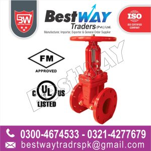
Gate valve: An on-off valve that works by inserting a rectangular gate or wedge into the flow of the fluid. The fugitive emission standard for gate valves is covered by API 624 and ISO 15848-1. It should be noted that the stem motion in a gate valve is typically linear, which creates a lot of friction between the valve stem and packing. This friction can cause packing wear and tear as well as leakage. Gate valves are available in different types, such as slab, expanding and wedge. Wedge gate valves have a sealing element in the shape of a wedge. A wedge gate valve is a torque seated valve, meaning that the wedge is expanded from both sides due to the stem force and provides sealing. The expansion of the valve closure member due to the stem axial force is called “wedging effect.” Expanding gate valves are also torque seated valves with a closure member in two sections, one male and the other female. Slab gate valves have a flat disk or closure member that provides sealing due to the fluid pressure. Slab gate valves, unlike expanding and wedge gate valves, are not torque seated.
4.3.1 Height
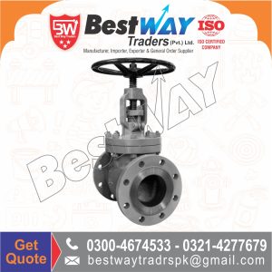
Gate valves have more height than ball valves due to their high body and upward stem and gate movement for rising stem design. The height of a gate valve could be considered a disadvantage, since it can impose a manifold structure with higher height. Usage of a linear actuator on top of a TCG valve could make the height differential even greater compared to an actuated ball valve. One should bear in mind that rack and pinion or scotch and yoke actuators, which are used for ball valve automation, stand horizontally when the valve is connected to a horizontal pipe, whereas linear actuators stand vertically when the TCG valve is connected to horizontally installed piping. Fig. 4.33 illustrates the height of an actuated slab gate valve.
Gate valves or ball valves are two typical valves used in the manifolds. Gate valves have a long history of use in subsea blowout preventer (BOP) stacks, trees, and manifolds and are considered relatively reliable devices because both the valve and the valve actuators have been through extensive development with proven field use and design improvements. Figure 19-6 illustrates two types of subsea gate valves. Figure 19-6A shows a WOM(Worldwide Oilfield Machine, Inc.) subsea gate valve with actuator, compensator, and ROV bucket. The hydraulic actuator is designed with a fail-safe model and spring returns with the ROV. The mechanical ROV is for backup. Figure 19-6B shows a WOM subsea gate valve with only an ROV bucket. Both valves are designed, built, and tested based on API 6A [6] and 17D [7], which can be used up to a water depth of 13,000 ft (4000 m).
Gate valves are used when a straight-line flow of fluid and minimum flow restriction are needed. Gate valves use a sliding plate within the valve body to stop, limit, or permit full flow of fluids through the valve. The gate is usually wedge-shaped. When the valve is wide open, the gate is fully drawn into the valve bonnet. This leaves the flow passage through the valve fully open with no flow restrictions. Therefore, there is little or no pressure drop or flow restriction through the valve.
Gate valves are not suitable for throttling volume. The control of flow is difficult because of the valve’s design and the flow of fluid slapping against a partially open gate can cause extensive damage to the valve. Except as specifically authorized by the manufacturer, gate valves should not be used for throttling.
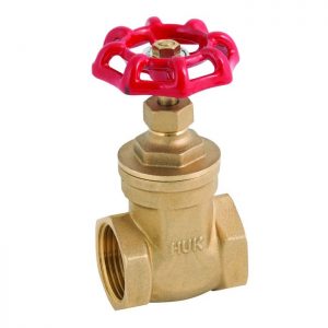
Gate valves are classified as either rising-stem or non-rising-stem valves. The non-rising-stem valve is shown in Figure 7-2. The stem is threaded into the gate. As the handwheel on the stem is rotated, the gate travels up or down the stem on the threads while the stem remains vertically stationary. This type of valve will almost alway
ate and globe valves can have fire test certificates according to API 6FA or ISO 10497 standards. The fire test certificate is not usually required for gate and globe valves with no nonmetallic parts. A fire test guarantees that the valve will function properly during a fire. ATEX is the European regulatory framework for manufacturing, installation, and use of equipment in explosive atmospheres. ATEX certification indicates that the valve does not have any source of ignition, which is applicable for equipment in potentially explosive atmospheres. Valves with actuators are usually in the ATEX scope of work because the ATEX directive does not consider the process source of ignition inside ATEX. Only external sources of ignition such as actuators with electrical parts make the valve fall inside ATEX.
Reviews
There are no reviews yet.